
TM 5-3805-296-23-6
0417
PILOT CONTROL HOSES INSTALLATION CONTINUED
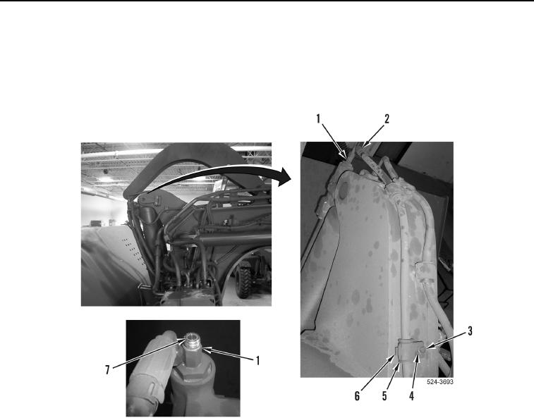
16. Install two insulations (Figure 35, Item 6), clamps (Figure 35, Item 6), washers (Figure 35, Item 2), and bolts
(Figure 35, Item 1) on pilot control hose (Figure 35, Item 2) and machine.
17. Install new O-ring (Figure 35, Item 7) on fitting (Figure 35, Item 1).
18. Install left upper inner pilot control hose (Figure 35, Item 2) on fitting (Figure 35, Item 1).
Figure 35. Left Inner Quick Drop Pilot Control Connection.
0417

