
TM 5-3805-296-23-6
0390
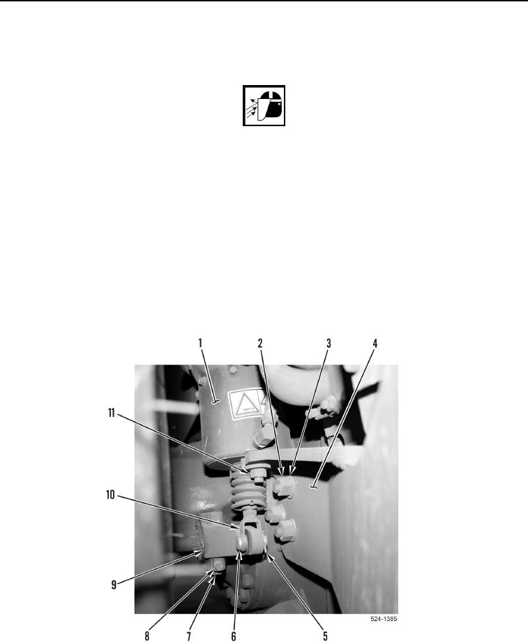
LEFT FENDER BRACKET INSTALLATION
000390
1. Install bracket (Figure 12, Item 4) on machine with three washers (Figure 12, Item 3) and new locknuts
(Figure 12, Item 2).
WARNING
Ensure that brake actuator yoke is clear of machine and personnel and release parking
brake to apply tension in brake actuator. Failure to follow this warning may result in injury
or death to personnel or damage to equipment.
2. Release parking brake (TM 5-3805-296-10).
3. Position brake actuator (Figure 12, Item 1) on bracket (Figure 12, Item 4) and tighten two nuts
(Figure 12, Item 11).
4. Secure slack adjuster (Figure 12, Item 9) and yoke (Figure 12, Item 10) together with pin (Figure 12, Item 6).
5. Install new cotter pin (Figure 12, Item 5) in pin (Figure 12, Item 6).
6. Rotate worm shaft (Figure 12, Item 7) until slack adjuster (Figure 12, Item 9) is tight against pin
(Figure 12, Item 6).
7. Tighten lock bolt (Figure 12, Item 8).
8. Remove wheel chocks from front and rear of rear tractor tires and apply parking brake (TM 5-3805-296-10).
Figure 12. Bracket.
0390
END OF TASK

