
TM 5-3805-296-23-5
0324
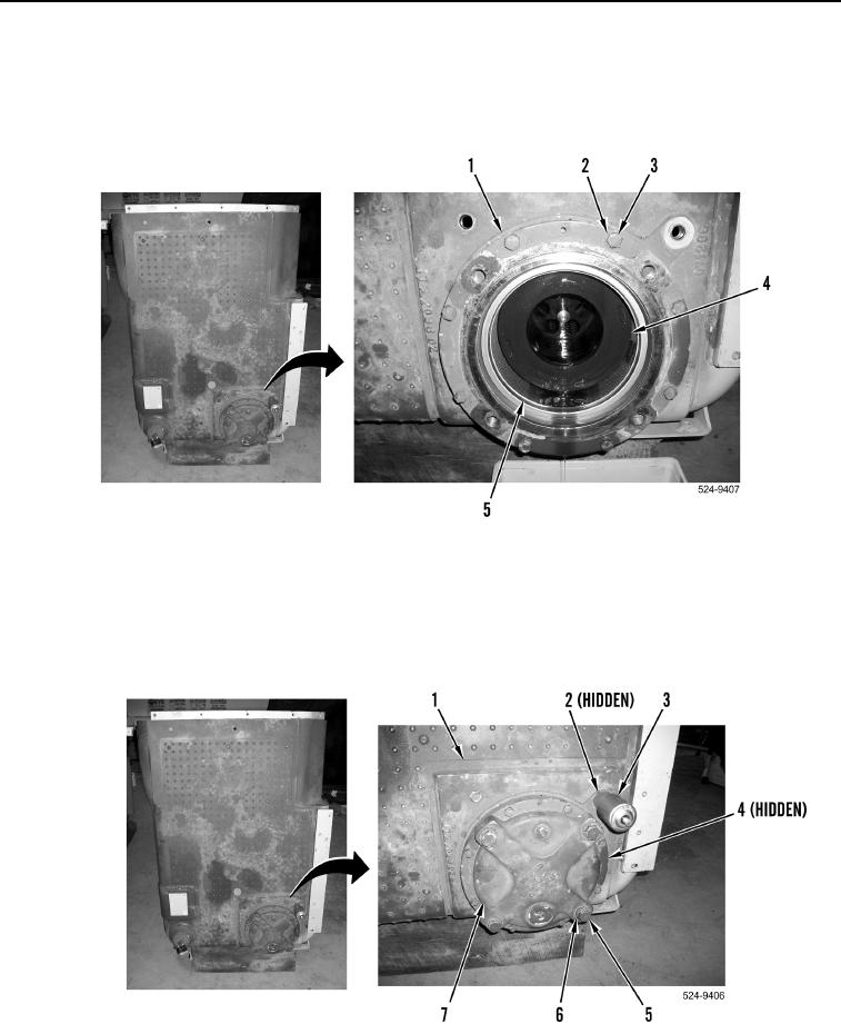
ASSEMBLY CONTINUED
22. Install eight washers (Figure 43, Item 2) and bolts (Figure 43, Item 3) on hydraulic oil tank (Figure 43, Item 1).
23. Install screen (Figure 43, Item 5) on hydraulic oil tank (Figure 43, Item 1).
24. Install two oil filters (Figure 43, Item 4) on hydraulic oil tank (Figure 43, Item 1).
Figure 43. Hydraulic Oil Filter.
0324
25. Install new O-ring (Figure 44, Item 4), filter bypass valve (Figure 44, Item 7), four washers (Figure 44, Item 6),
and bolts (Figure 44, Item 5) on hydraulic oil tank (Figure 44, Item 1).
26. Install new O-ring (Figure 44, Item 2) and check valve (Figure 44, Item 3) on hydraulic oil tank
(Figure 44, Item 1).
Figure 44. Bypass Valve.
0324
END OF TASK

