TM 9-4940-568-34
3-157
3-46. MANUAL OVERRIDE VALVE REPAIR
THIS TASK COVERS:
a. Removal
b. Disassembly
c. Assembly
d. Installation
INITIAL SETUP
Tools
Tool Kit, General Mechanic’s
(Item 67, Appendix F)
Materials/Parts
Sealing compound (Item 29, Appendix B)
Tags, Identification (Item 36, Appendix B)
Cap and plug set (Item 6, Appendix F)
Gasket (Item 9, Appendix E)
Materials/Parts - Continued
Lockwashers (2) (Item 45, Appendix E)
Packing, preformed (Item 113, Appendix E)
Packing, preformed (Item 104, Appendix E)
Seal, safety lock (Item 159, Appendix E)
Equipment Condition
FRS unloaded, (TM 9-4940-568-10).
Batteries disconnected, (TM 9-4940-568-10).
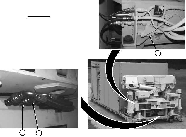
a.
Removal
NOTE
Tag and mark all hoses and
connectors prior to removal.
Cap and plug hydraulic hoses
and tubes after removal.
The
hydraulic
system
operates at high pressures.
Never
disconnect
any
hydraulic line or fitting
without
first
dropping
pressure to zero. Failure to
comply may result in serious
injury or death to personnel.
WARNING
(1) Position drain pan under manual
override valve (1).
(2) Remove hydraulic line quick disconnect
(2) from crane supply line (3).
2
3
1