
TM
3-4240-309-20&P
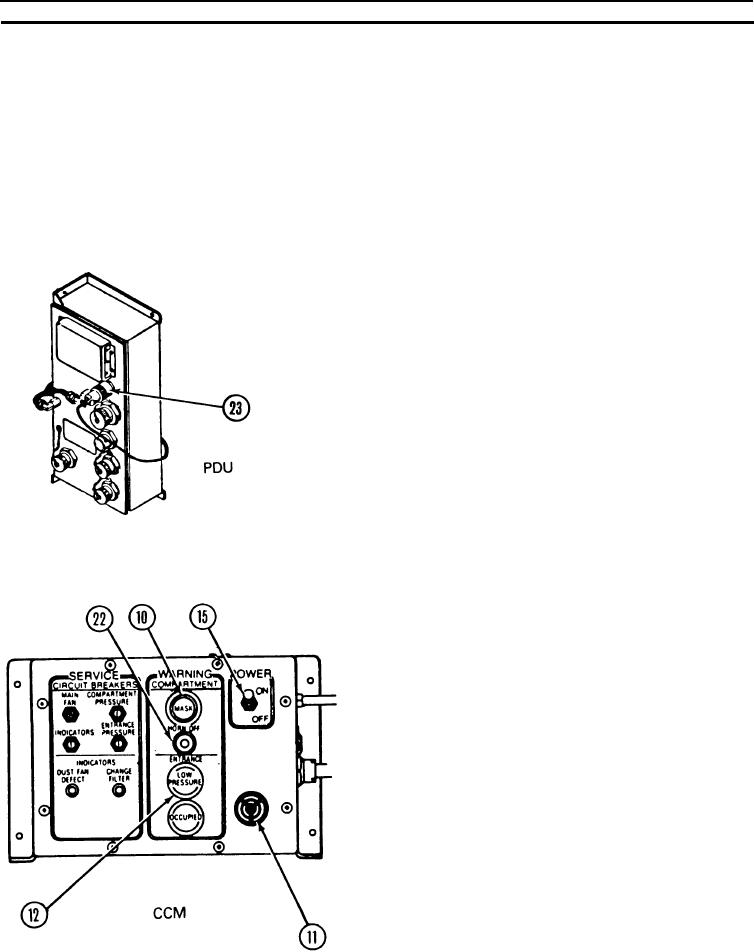
lNDICATION/REMARKS
ACTION
ITEM
LOCATION
Main fans must start and
Ensure that all van doors
Pressure circuit
CCM
run.
are closed. Ensure that
PE doors on vans 1 and 4
are closed. Leave
interconnecting doors
open.
Set POWER switches (15)
in vans 2 and 3 to ON.
MASK switch/indicator
lights (10) will flash in
vans 2 and 3. Warning
horns (11) will sound in
vans 2 and 3.
After 10 seconds,
This will lock airflow
disconnect plug P2 (23)
valves in fully open
from connector J2 on
position.
PDUs.
Set POWER switches (15)
MASK switch/indicator
in vans 1 and 4 to ON.
lights (10) will begin
flashing in vans 1 and 4.
Warning horns (11) will
begin to sound in vans 1
and 4.
Allow warning horns to
MASK switch/indicator
silence automatically.
lights (10) in each van
This will indicate proper
will go off and warning
system operation.
horns (11) will silence
when proper van
pressure is reached
(approximately 30
seconds).
ENTRANCE LOW
PRESSURE switch/
indicator lights (12) on
vans 1 and 4 will light
when filter unit is started
and then go off when
proper PE pressure is
reached (approximately
30 seconds).
When loss of power to
CPE occurs with the
CCM POWER switch in
ON position, MASK
switch/indicator lights
(10) will flash and
warning horns (11) will
sound for the affected
van.
2-9