
TM 3-4240-302-30&P-3
(2) The protective entrance provides a
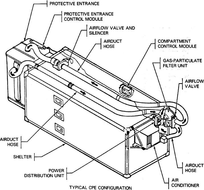
c. Typical CPE System Description.
pressurized transition area between the
(1) The gas-particulate filter unit (GPFU)
shelter and the outside contaminated
removes toxic gases and dust from the air
zone.
Personnel entering from the
supplied to the protective entrance and
outside must wait 5 minutes within the
shelter. Outside and return air is drawn by
protective entrance before entering the
the main fan through the air inlet of the filter
shelter. Contamination is purged by the
unit. From the main fan, the air is pushed
flow of filtered air.
The PECM
through the particulate and gas filters to the
automatically adjusts the airflow valve
airflow valve.
The filtered air passes
and silencer assembly to maintain the
through the airflow valve and is carried by
proper air pressure inside the protective
airduct hoses to the protective entrance (PE)
entrance.
through the airflow valve and silencer and to
d. CPE System Configurations.
Collective
the shelter through the air conditioner.
protection equipment is configured to fit the needs of a
Pressure sensing components in the
specific application and may differ from the typical
compartment control module (CCM)
system discussed above.
automatically adjust the airflow valve to
maintain a positive pressure in the shelter.
1-2