
TM 5-3805-296-23-6
0417
CONTROL VALVE HOSES INSTALLATION
000417
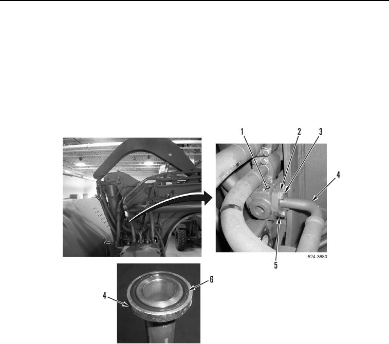
47. Install new O-ring (Figure 51, Item 6) on hydraulic hose (Figure 51, Item 4).
48. Install hydraulic hose (Figure 51, Item 4), two flange halves (Figure 51, Item 5), four washers
(Figure 51, Item 2), and bolts (Figure 51, Item 3) on hydraulic line (Figure 51, Item 1).
NOTE
Remove plugs and caps from hydraulic hoses and fittings.
Install hydraulic hoses as noted during removal.
Install hydraulic hoses as tagged and marked during removal.
Figure 51. Bowl Down Line Connection.
0417

