
TM 5-3805-296-23-5
0312
INSTALLATION
000312
NOTE
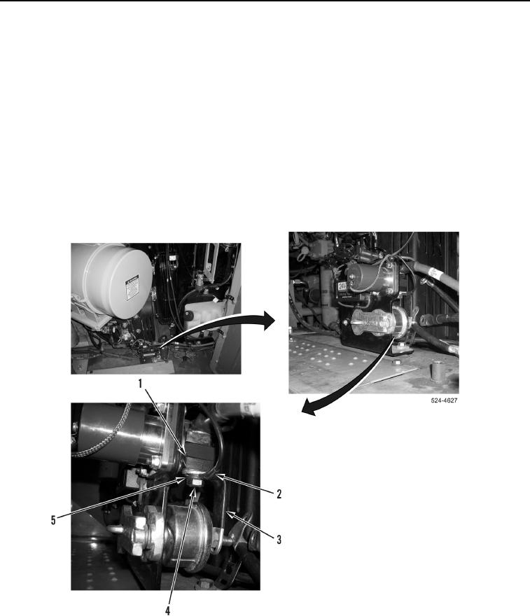
Install lockout switch and battery disconnect switch as noted during removal.
1. Install battery disconnect switch (Figure 3, Item 3) on bracket (Figure 3, Item 2).
2. Install lockout switch (Figure 3, Item 5), new lockwasher (Figure 3, Item 1), and nut (Figure 3, Item 4) on
battery disconnect switch (Figure 3, Item 3).
NOTE
Install bus bar as noted during removal.
3. Install bus bar (Figure 4, Item 3), wire (Figure 4, Item 2), new lockwasher (Figure 4, Item 5), and bolt (Figure 4,
Item 4) on NATO slave receptacle (Figure 4, Item 1).
Figure 4. Battery Disconnect Ground Bus Bar.
0312

