
TM 5-3805-296-23-5
0301
REMOVAL CONTINUED
9. Position splash shield (Figure 4, Item 1) aside.
Figure 4. Splash Shield.
0301
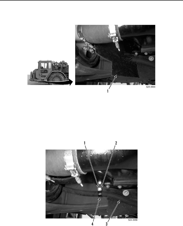
NOTE
Note location and orientation of P-clamp to aid in installation.
10. Remove bolt (Figure 5, Item 1), washer (Figure 5, Item 2), and P-clamp (Figure 5, Item 4) from machine.
11. Remove P-clamp (Figure 5, Item 4) from hydraulic hose (Figure 5, Item 3).
Figure 5. Hydraulic Hose and P-clamp.
0301

